← Назад

Оптимальная пиковая деконволюция.

Optimal Spike Deconvolution.

SPD Интерактивная обрабатывающая программа.

DESIGNATION

 The program is intended for a zero-phase and minimum-phase spike deconvolution (Spike) in frequency or time domain and for predictive deconvolution (Pred) of traces of downgoing and upgoing waves obtained after selection of initial wavefield on waves separation program " Wave correlation and subtraction ", and also for deconvolution of the initial field traces.

  The data can be three-component and multipoint.
  The deconvolution in the frequency domain can be carried out both in customary (Spike), and in optimum (Opt) modes (traces of the residua after separation of waves in this case are used). The inverse operator can be calculated for each trace or for some given trace and applied to all traces. The operator is calculated in a given window from the set a priori first break hodograph. The first break hodograph can be edited. In a mode of a zero- phase deconvolution the linear and nonlinear editing of spectrums of traces of upgoing and downgoing waves after deconvolution, if the spikes are present, and also reduction on the power of resulting traces to a level of amplitudes of the input traces is provided.
  The convolution of the deconvolution operator with traces can be yielded in frequency (for all types of operators) or in a time domain (for operators predictive (Pred) or spike (Spike) deconvolution in a time domain (Time Domain)).
  The bandpass filter with the trapezoidal characteristic, which is applied to weakening noises after deconvolution, in special cases can look like (high-cut filter) HCF or (low-cut filter) LCF. The LCF in the bandpass filter can be both zero-phase, and minimum-phase.
  In the program saving the operator of deconvolution in the table of LDB such as SIGINFO in that domain in which it was obtained (in frequency or time) is provided. The saving of trace fragment of downgoing waves in the given time window in a time domain in the table of LDB such as SIGINFO is provided too.

Main panel of the program

The main panel of program looks like:

The main panel of the program:Spike Deconvolution consists of four frames (from above downwards): the main menu, Draw-areas, toolbar and string of the messages.

The main menu

The main menu:

is located at the top of the main panel

Menu File

Contains items of the vertical pulldown menu:
Project
Open downgoing wave
Close
Exit

The item Project

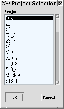
Will open the dialogue panel Project Selection , intended for choice and installation of the project, from which one the modifications, hodographs, table of a LDB will take.

The project is set after pressing the button ??.

The item Open downgoing wave

After pressing the button Open downgoing wave.., if the project was set, the standard dialogue of selection of modification is displayed and the modification of downgoing waves which will be used for estimation of the inverse operator is selected.

and modification of downgoing waves is selected, which will be used for calculation of the inverse operator. If the project was not set, the dialogue of the project choice at first is called.
 The operator is estimated on one of components P-Z-1. If in modification of such components is not present, the error message is produced and the modification is not opened.
  After call of downgoing waves modification the buttons Hodograph (FB) and Deconvolution of the main menu of the program are opened. The called modification is visualized in a field of traces (Draw-area).
  To the obtained profile image it is possible to apply all tools of the menu item View and toolbar in the bottom of the main panel (as in all interactive programs).

The item Close

The modification figured in a field of traces, is closed, the field of traces (Draw-area) is cleared.

The item Exit

The main panel of the program is closed, the operation with the program is ended.

The item View

The item View contains items of the vertical pulldown menu:

Undo
cancellation of the last variant of visualization in Draw-area and return to the previous variant,
Redo
return to variant of visualization canceled by the latter Undo,
Zoom in
transition in the mode of image increase,
Zoom out
transition in the mode of image decrease,
Info mode
transition in the mode of obtaining of the information about traces,
Manual zoom...
image scale setting in digital form,
Zoom all
drawing of all modification in Draw-area,
Options...
visualization parameters setup

  In the user's guide on the program "The first breaks definition (FBD) " is described operation with View menu items.

Menu Hodograph(FB)

Contains items of the vertical pulldown menu:

Load...
Clear
Save...
Edit

The item Load...

  After pressing the button Load.. the panel Load FB hodograph is opened.
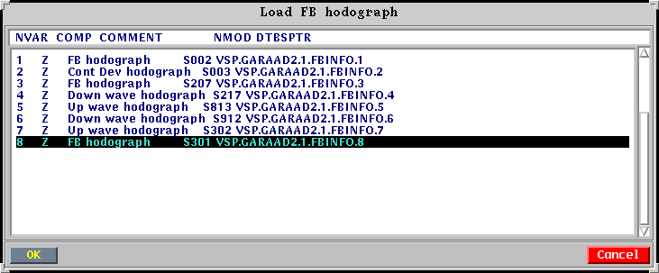
In this panel the a priori hodograph of first breaks (FB hodograph), calculated in the program FBD or phase hodograph of downgoing wave (Down wave hodogarph) is selected from the list of the tables of LDB such as FBINFO. After pressing OK it is drawn on the screen.It can be looked in the enlarged form, to edit, pressing the left key of the mouse in the mode Edit... or Rule (Pencil) in the panel of icons.The edited hodograph can be saved after pressing the button Save..., indication of the necessary component in the panel Hodographs Saving Options and selection of the table of LDB for saving in the panel Save Calc. Hodograph.

The item Clear

After pressing the button Clear the field of hodograph in memory is cleared and its image from the screen is cleaned.

The item Save...

Is intended for choice in the table FBLIST of string with a name of hodograph or new string for record of hodograph and saving of hodograph visualized in a field of traces (Draw-area) in the appropriate table FBINFO.

After pressing the button Save... will be opened ?t first panel Hodographs Saving Options, in which is set the component of saved hodograph. After pressing the button ?? in this panel the panel Save Calc. Hodograph will be opened,

the string with name of hodograph or new entry is selected from which one mouse, where the hodograph will be saved. After pressing the button ?? in this panel the hodograph is saved.

The item Edit

Is intended for editing a hodograph in a field of traces. After its activation the edit mode of hodograph is installed, in which after of each pressing of the left key of the mouse in trace nearest to a point of Draw-area, pointed by the cursor, the new node of hodograph will be is brought. Thus the old node on this trace is cleared. Any node of hodograph can be deleted by pressing of the right key of the mouse. The edit mode is closed at transition in any other mode of operation with field of traces (for example Zoom in).

Menu Deconvolution

Contains the item of the pulldown menu Set Parameters.

After pressing the button Set Parameters there is a panel Spike Deconvolution Parameters, consist of three data blocks: Operator Creation, Data, Operator Parameters, progress-indicator and actions buttons

At opening of the dialogue panel in it the parameters from the file JOBS/SPD.parare set, if it exists. If this file does not exist, the parameters by default are set.
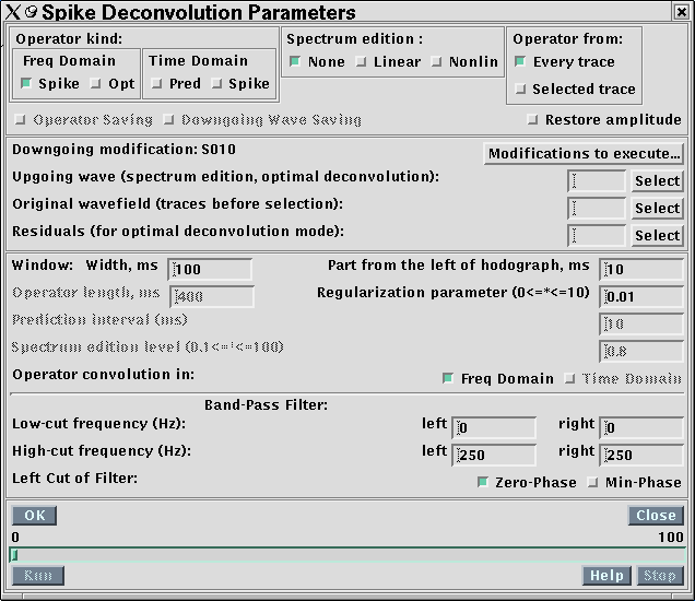
The block data Operator Creation

Is intended for the definition of the operator kind and method of its application.

At first is selectedthe type of the operator of deconvolution (Operator kind). The variants are possible:

Frequency domain (Freq Domain), spike deconvolution (Spike).
Spike deconvolution in frequency domain with a customary regularization of the operator.
Frequency domain (Freq Domain), optimum deconvolution (Opt)
Spike deconvolution in frequency domain with an optimum regularization. As a regularization term the ratio of a power spectrum of noises to a power spectrum of an impulse seismogram is applied./EM>
  For job requires modification of reflected waves and modification of the residues after the procedure of selection. It should be applied on short-distance shot points, it is desirable together with editing of traces spectra after deconvolution. The operator for each processed depth is desirable to estimate.
Time domain (Time Domain), predictive deconvolution (Pred)
Is applied both to nearest and to the offset shot point. This mode should be applied before the procedure of selection, the operator should be calculated on one traces. An interval of prediction must be greater - about 20 ms.
  In this mode restoring amplitudes is unavailable.
Time domain (Time Domain), spike deconvolution (Spike).
Is applied for offset SP, it is necessary to use in the mode of creation of the operator on one trace. Allows to regulate a size of dist?rtions area before the first breaks (Part from the left of hodograph) and length of the deconvolution operator (Operator length).

Further is selected the deconvolution operator estimation mode (Operator from). Variants:

on each trace of input modification
In this case the operator is calculated on each trace of modification. The calculated operator is applied in the following way: if one depth corresponds to the logical number of a magnitogram of input trace, in output modifications all traces having this number (set according to magnitogram) are calculated. If several cable depthes correspond to one number, the calculated operator processes only traces which have appropriate number of the magnitogram and cable depth. The traces, which do not satisfy to these requirements, are ignored and are not written to output modifications.
on a selected trace
In this mode all traces of input modifications are processed. The operator is calculated on traces selected interactively up to start of the dialogue. If the traces were not selected, it is impossible to enter this mode. At selection of the traces for creation of the operator it is necessary to use traces outside of area of head waves. The deepest traces from modification are selected as a rule.

Traces spectra edition after deconvolution (Spectrum edition):
The mode (None, Linear, Nonlin) is set and the level of editing (Spectrum edition level) spectra upgoing and downgoing waves after deconvolution is set. None - the editing is not preset. The edit mode (Linear, Nonlin) becomes accessible after the definition of uprising waves modification(Upgoing wave).
  The purpose of editing is the decrease of values of spikes in a spectrum of upgoing waves or initial traces relatively spectrum Z (P) - component of downgoing waves after their deconvolution according to a set level of editing. On each frequency of a spectrum the coefficient of editing is determined by multiplying an value of level of editing by value of spectrum Z(P)-component of downgoing waves after deconvolution. If the value of spectrum of an upgoing wave exceeds this level, it is substituted by value of level. All components of upgoing waves are edited.
  During nonlinear editing (Nonlin) the spectrum of the main component of downgoing waves after deconvolution remains without change.
 During linear editing(Linear), the spectrum of the main component of downgoing waves after deconvolution is edited in a way to save the ratio of amplitudes of spectral components of downgoing and upgoing waves spectrums after their editing.
  For editing a field before selection (Original wavefield) the value of the parameter of editing is increased on 1, then the nonlinear editing is used.

Operator saving (Operator Saving)
 Option, setting the deconvolution operator saving mode after its estimation in the mode Selected trace.
 After operator estimation there is a dialogue panel Select operator saving table, from which the mouse cursor selects the table, in which the operator will be saved. After pressing ?? the operator is saved.

  The operator is saved in frequency representation, if it was estimated in frequency domain (the option Operator convolution in Freq Domain) is switched on. If it was estimated in a time domain (the option Operator convolution in Time Domain) is switched on, it is saved in time representation.
  At saving the operator in frequency representation the real and imaginary part of its complex spectrum are written accordingly in columns REAL and IMAGE of the table SIGINFO. In columns FREQ and AFREQ the frequency values in Hz and circle frequency in rad/sec are written accordingly. At saving the operator in time representation its amplitude are written in a column SIGNAL, and times - in a column TIME in ms. For the left part of the double-sided operator obtained in the mode Spike in Time Domain, the negative values of times are written.

Saving of the downgoin wave form (Downgoing Wave Saving)
  An option installing the mode of saving of an downgoing wave as of the time function in the mode Selected trace.
  After pressing the button Downgoing Wave Saving there is a dialogue panel Select wave saving table, from which the mouse cursor selects the table, in which the downgoing wave will be saved. The name of the selected table is set in the table- ist SIGLIST after pressing ??.
  After reading selected (highlighted by green colour) trace of an downgoing wave of amplitude of an downgoing wave in the given window for the given trace, the boundaries which are indicated in visualization field of traces, is saved in a column SIGNAL, and times - in a column TIME in ms.

Amplitudes of traces restoring after deconvolution (Restore amplitude)
  After setting of an option Restore amplitude the reduction of amplitude of downgoing wave after deconvolution to value of amplitude for dominant frequency of this wave before deconvolution is carried out.

The block Data

The block Data is intended for selection of modifications, necessary for processing
Downgoing modification: _____
Name open and visualized in a field of traces of modification of downgoing waves.
Modifications to execute...
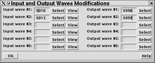
  This button calls the dialogue panel Input and Output Waves Modifications, in which are set input (Input wave) and output (Output wave) modification.

 The name of modification of downgoing waves in Input wave #1 ____ is set automatically after opening of input modification. A name of modifications of upgoing waves (Upgoing wave) and initial wave field (Original wavefield) automatically rewrite from appropriate fields of the panel Spike Deconvolution Parameters in fields Input wave of the panel Input and Output Waves Modifications with next number.
 The program fulfils a deconvolution only of those modifications from the list, for which the output modifications are preset.
Upgoing wave
Upgoing wave is necessary for editing of a spectrum and for an optimum frequency deconvolution. At its definition or change the given modification is automatically brought in the list of input modifications.
Original wavefield
Wave field before selection. At editing spectrums after deconvolution is processed by the special manner. At its definition or change the given modification is automatically brought in the list of input modifications.
Residuals
The residues after the procedure of selection. It are required at an optimum deconvolution.

The block data Operator Parameters

In this data block the parameters for the operator calculation are set:

Window: Width, ms
Width of the window in area of a first break, on which the operator of deconvolution is estimated.

Part from the left of window, ms
Shift of the above described window to the left with respect to a first break.

Operator length, ms
Length of the predictive deconvolution operator or double-sided operator of spike deconvolution (in the mode Spike in Time Domain).

Regularization parameter
The regularization parameter (0<alf<10) of inverse operator. Than less parameter value, the more resolution of traces and is more an noises level after deconvolution.

Prediction interval
Interval of a prediction in ms for the operator of predictive deconvolution. The operator of predictive deconvolution tends to compress a signal up to the prediction interval value. The less interval, the more rigidly deconvolution and is higher a noise level.

Spectrum edition level
Level of editing of a spectrum after deconvolution 0.1<=lev<=100. The less parameter value, the more hard editing (is suppressed the greater number of spike pips in a trace spectrum of upgoing waves after deconvolution, among which, except for the sharply expressed pips, there can be pips with less expressed amplitudes. Excessively low level of editing can give in essential dist?rtion of a spectrum and poor result of a deconvolution. Recommended Value 0.8. The spectrum editing is possible only at the definition of upgoing waves modification.

Operator convolution in: Freq Domain, Time Domain
Convolution of the operator with trace in frequency or time domain. The convolution of the operator in frequency domain is possible for all kinds of the operator (Operator kinds). The convolution of the operator in a time domain is possible only for operators calculated in a time domain (Pred or Spike in time domain ). At the definition of convolution in a time domain to the calculated operator the minimum-phase HPF is applied only, and the LPF is not used.

Band-Pass Filter:
Parameters of frequency response of the trapezoidal bandpass filter:
Left low-cut frequency (Hz)
       the left frequency of a low frequency cut of filter (LLF) (Hz),
Right low-cut frequency (Hz)
       the right frequency of a low frequency cut of filter (RLF) (Hz), DD>Left high-cut frequency (Hz)
       the left frequency of a high-frequency cut of a filter (LHF) (Hz),
Right high-cut frequency (Hz)
      the right frequency of a high-frequency cut of a filter (RHF) (Hz).
The parameters of the bandpass filter should satisfy to a condition:
      LLF <= RLF <= LHF <= RHF.
For LPF: LLF = RLF <= LHF <= RHF.
For HPF: LLF <= RLF <= LHF = RHF.

Left Cut of Filter Zero-phase Min-phase
Flag of filter kind setting for the left cut filter (HPF): zero- phase (Zero-phase), importing some dist?rtion in area of trace before the first break of a direct wave, or minimum-phase (Min-phase), not distorting this area.
  The bandpass filter is applied as a sequence of two filters: a HPF defined by parameters Left and Right low-cut frequency, and LPF defined by parameters Left and Right high-cut frequency. The LPF always zero-phase, and HPF can be both zero-phase, and minimum-phase.

The actions buttons of Spike Deconvolution Parameters panel

OK
Setting of given parameters and options, saving them in the file JOBS/SPD.par. In a field of traces along hodograph are drawn boundary of the window for operator calculation. The values of window parameters can be changed and again to press ??.
Close
closing of the panel, cancellation of the made settings,
Run
The initializing of the deconvolution process, is possible only after parameter setup (pressing of the button ??). The course of the process is demonstrated by the progress-indicator. In string of the information of the main panel of the program the information on number of the processed trace is output. Upon termination of the process is informed, that the process was successfully finished and how many traces were processed.
Stop
Process interrupt of a deconvolution by the user.

Menu Help

Contains items of the vertical pulldown menu:

Contents...
The hint call
Users Guide - >
The user's guide call

Toolbar

The toolbar is the same, as in the program of subtraction of waves, except for the added button for selection of traces for the mode of the operator estimation on one trace .

After pressing an selection button of a trace it is possible in a field of visualization of traces to select a trace, on which the operator will be estimated, to bring to it a mouse cursor and after a click by the left mouse button it to select . For cancellation of selection of trace it is necessary to click with the right mouse button. The selection of one trace automatically cancels selection another.

Contacts
43, Zaitseva st., room 263, Saint Petersburg, 198188, Russia
Phone:
+7 (495) 754-9990
+7 (903) 255-7275
+7 (911) 236-7708
e-mail:
vsp@geovers.com
© 2001-2024 GEOVERS Ltd.